ATmel and AVR chips
If you are interested in comparisons between microcontrollers, see this post.
AVR is a modified Harvard 8-bit RISC single chip microcontroller
The ATmel site has some interesting application notes related to some not trivial aspect:
- AVR040: EMC Design Considerations
- AVR042: AVR Hardware Design Considerations
- AVR Looping
- ATmega48A/PA/88A/PA/168A/PA/328/P
The advice is to read the datasheets that contain a lot of info and working examples, for example the ATMEGA32U4 one (here the mapping with the Arduino Leonardo's pins).
The information below are intended to be generic, but it's possible that referrers to the ATMega32U4.
Some weird naming is going on, for example, ATMega32u4-AU means use external clock, instead
ATMega32u4-RC uses internal clock or -AUR meaning reel.
The reference for the avr-libc is here.
Datasheets
Use the datasheet of a chip to understand the working and the functionality of it.
There are little things to know in order to order the right incarnation of a chip, for example in the section named ordering information.
Be aware of some discrepancies inside the datasheet: for example for the atmega16u2 is indicated the default clock as internal but if you read the default fuse is set as external
Memory
This kind of microcontrollers have three types of (linear) memory
- flash: contains the code
- SRAM: contains the running data (registers, I/O, RAM)
- EEPROM: contains the static data (not present in all the chips)
The program flash memory space is divided in two sections, the Boot Program section and the Application Program section; each one has dedicated lock bits for write and read/write protection.
Clocks
Each subsystem of an AVR chip has its own clock that is possible to deactivate in order to reduce power consumption; so the maximum speed is achievable only with a lot of power consumption.

there are come common choices for the clock source:
- external crystal/resonator (low power or full swing)
- external clock (by the
XTAL1pin) - internal (calibrated) RC oscillator
each one is selected by the CKSEL register.
Probably all the modern ATmel microcontrollers are described with fully static operation, that seems to indicate that can be clocked with arbitrary frequencies (look at this stack overflow question or this post on AVRFreaks).
If you use an external oscillator take in mind that you need a specific value
of capacitor to associate with (read the related section, for an ATMega32U4 is 12-22pF).
Fuses
The fuses are special memory spaces that can be modified only by a programmer and that decides certain configuration with which the chip will run.
Note: some modification to these values can brick the chip, so use caution!
-
Some indication about FUSE settings: in particular
What's notable is that the default fuse setup for an Arduino (here) will set the high fuse to 0xD6. This sets up the Arduino so on boot it will boot the bootloader. In other words, code execution will not begin at address 0x0000. This won't work if you have no bootloader. The fuses need to be changed so that the BOOTRST flag is unprogrammed. In AVR-speak, this means it's set to a value of 1 (0 means "programmed). So, this means that the high fuse needs to be set to 0xD7. No other fuses need to be changed.
Links
Timers&Interrupts
The AVR chips have available a certain numbers of counter that can be used as clock
in an application, and some of these are connectable with interrupts in some cases.
They are used also to generate accurate PWM signals via I/O pins.
Can exist more than one counters/timers with difference number of bits (usually 8 or 16).
First of all is needed to set the prescaler with the flags CSx[0:2], usually are
in powers of two
Below a piece of code that use the Timer0 counter (that is a 8bits counter) to raise the interrupt
(i.e. fire after 256 cycles); the counter has a prescaler of 1024 and is used with a 8MHz clock so we obtain
i.e. 30Hz.
void init_timer() {
    TCCR0B |= _BV(CS00) | _BV(CS02); // clk/1024
    TIMSK0 |= _BV(TOIE0);            // enable Timer0 Overflow Interrupt
}

ISR(TIMER0_OVF_vect) {
    // do stuffs
}

int main() {
    // change to 8MHz
    clock_prescale_set(clock_div_1);

    init_timer();
    sei(); // needed in order to enable interrupts

    while(1); // needed in order to don't crash the code (?)

    return 0;
}
or you can set an external interrupt
#include <avr/io.h>
#include <avr/interrupt.h>


int main(void)
{
    DDRD &= ~(1 << DDD2);     // Clear the PD2 pin
    // PD2 (PCINT0 pin) is now an input

    PORTD |= (1 << PORTD2);    // turn On the Pull-up
    // PD2 is now an input with pull-up enabled


    EICRA |= (1 << ISC00);    // set INT0 to trigger on ANY logic change
    EIMSK |= (1 << INT0);     // Turns on INT0

    sei();                    // turn on interrupts

    while(1)
    {
        /*main program loop here */
    }
}


ISR (INT0_vect)
{
    /* interrupt code here */
}
Low Level
When an interrupt happens
- the
CPUfinishes any pending instructions and then ceases fetching further instructions - Global Interrupt Enable (
GIE) bit is cleared - The
CPUfetches the instruction from the interrupt vector table that corresponds to the interrupt
It's important to note that the symbol's name (__vector_X where X is the entry's number
into the interrupts vector table) into the executable has the number shifted by one because
it starts omitting the RESET entry.
Links
- AVR130: Setup and Use the AVR® Timers
- http://www.avrfreaks.net/forum/tut-c-newbies-guide-avr-timers?page=all
- avr-libc page about interrupts
- Post from
avrbeginnerswith clear diagrams. - TimerOne library
- Quick and Dirty D to A on the AVR: A timer tutorial
- EXTERNAL INTERRUPTS ON THE ATmega168/328
Sleep modes
I/O
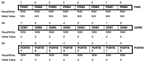
Three I/O memory address locations are allocated for each port
- Data Direction Register – DDRx: decides if that pin is input (logic zero) or output (logic 1)
- the Data Register – PORTx: in output mode decides the logic level, in input mode decides if the pull-up resistor is activated
- Port Input Pins – PINx: when the pin is in input mode, you can read from this register the logic value.
The Port Input Pins I/O location is read only, while the Data Register and the Data Direction Register are read/write.
The ports are bi-directional I/O ports with optional internal pull-ups
If some pins are unused, it is recommended to ensure that these pins have a defined level, floating inputs should be avoided to reduce current consumption in all other modes where the digital inputs are enabled (Reset, Active mode and Idle mode). The simplest method to ensure a defined level of an unused pin, is to enable the internal pull-up. In this case, the pull-up will be disabled during reset. If low power consumption during reset is important, it is recommended to use an external pull-up or pulldown. Connecting unused pins directly to VCC or GND is not recommended, since this may cause excessive currents if the pin is accidentally configured as an output.
Below an example of C code that blinks a led:
#include <avr/io.h>
#include <util/delay.h>

int main(void) {
    DDRC  = (1 << PC7);       //Sets the direction of the PC7 to output
    PORTC = (1 << PC7);       //Sets PC7 high

    while(1) {
        _delay_ms(500);     //Wait 500 milliseconds
        PORTC &= ~(1 << PC7); //Turn LED off

        _delay_ms(500);     //Wait 500 milliseconds
        PORTC |= (1 << PC7);  //Turn LED on
    }

    return 0;
}
Links
ADC
The ADC converts an analog input voltage to a 10-bit digital value through successive approximation. The minimum value represents GND and the maximum value represents the voltage on VCC, the voltage on the AREF pin or an internal 1.1V / 2.56V voltage reference.
To improve quality it's possible to activate the ADC noise reduction mode: it not only shuts down the CPU and I/O clocks, but it also triggers an ADC conversion after the CPU has stopped, and wakes everything back up once the ADC is done (but note that if you’re expecting I/O during the ADC sampling time, you’ll miss it.).
- http://nicecircuits.com/playing-with-analog-to-digital-converter-on-arduino-due/
- Tutorial about the
ADC
USI/SPI
This is the way to do serial communication with an atmel chip, it allows to create three and two wire communication (SPI is a three wire with a slave select channel implemented via software).
In the Attiny family there is the USI way, in the ATmega there is a SPI implementation.
TWI
- http://www.nongnu.org/avr-libc/user-manual/group__twi__demo.html
USB
Some chips have USB builtin
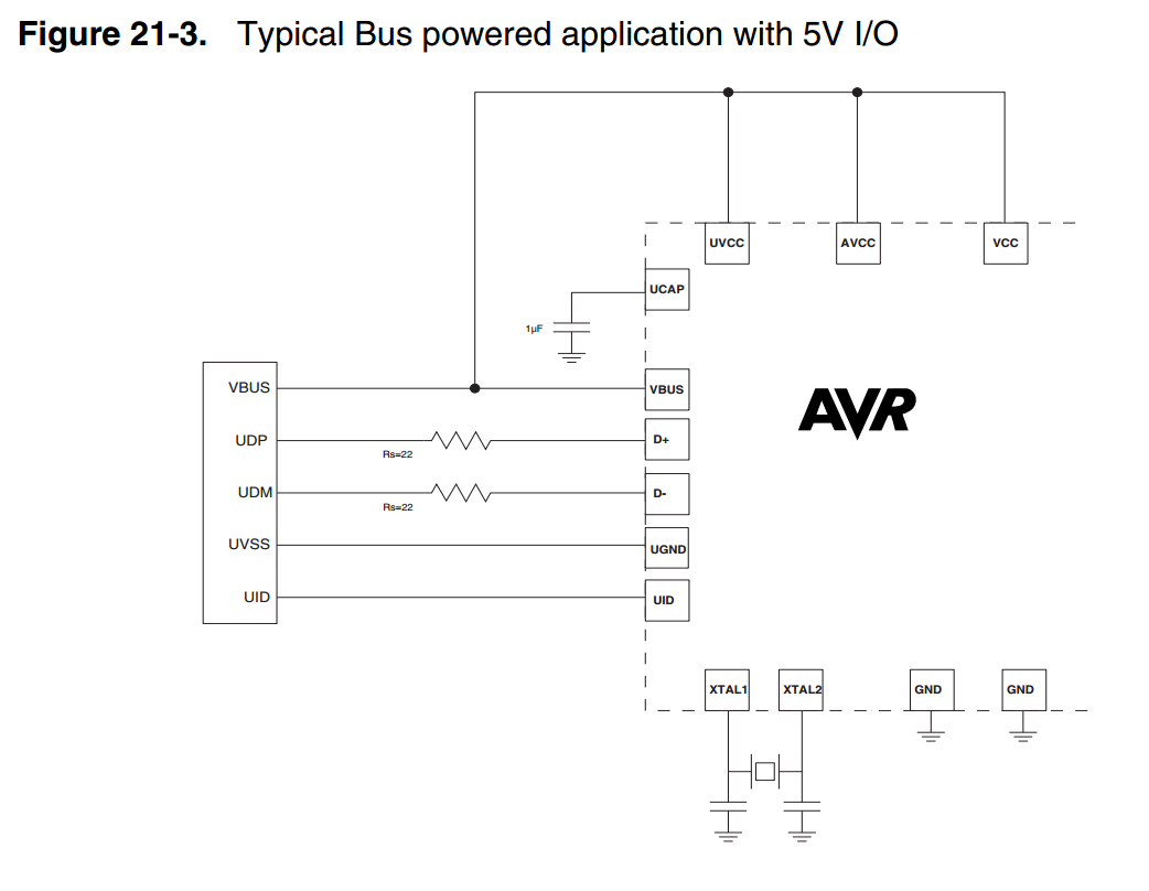
- LUFA: open-source complete USB stack for the USB-enabled Atmel AVR8 and (some of the) AVR32 microcontroller series,
You can read here an explanation Arduino related of an implementation of the USB circuitery.
Reset pin
It's possible to reset the chip presenting a low level on the RESET pin for longer than the minimum pulse length.
So, in order to not have a continuous reset, you need to pull up the RESET pin; generally if in your circuit you need
to reset the chip, a temporary switch is used
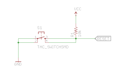
In parallel programming mode is possible to use 12V with this pin (it's the only one with which this is possible).
Take into account that there are more possibilities to reset the chip, read the section named System Control and Reset on the datasheet. A simple list is
- Power-on Reset. The MCU is reset when the supply voltage is below the Power-on Reset threshold (VPOT).
- External Reset. The MCU is reset when a low level is present on the RESET pin for longer than the minimum pulse length.
- Watchdog Reset. The MCU is reset when the Watchdog Timer period expires and the Watchdog is enabled
- Brown-out Reset. The MCU is reset when the supply voltage VCC is below the Brown-out Reset threshold (VBOT) and the Brown-out Detector is enabled.
- JTAG AVR Reset. The MCU is reset as long as there is a logic one in the Reset Register, one of the scan chains of the JTAG system.
- USB End of Reset. The MCU is reset (excluding the USB controller that remains enabled andattached) on the detection of a USB End of Reset condition on the bus, if this feature is enabled by the user.
You can read the source of the reset by the register MCUSR.
During reset, all I/O Registers are set to their initial values, and the program starts execution from the Reset Vector.
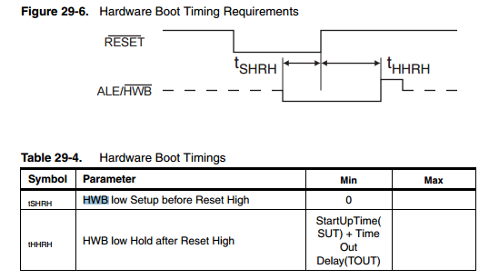
Boot
It's a little tricky the boot process: there are two fuse that you have to check in your
hardware to understand how boot: HWBE and BOOTRST
The pin PE2/HWB is a special pin that has a special function: if the fuse HWBE is enabled, during reset
this pin is sampled and the reset vector will be set as the boot loader reset vector;
the following is a diagram from the atmel's documentation
The Boot Reset Fuse (BOOTRST) can be programmed so that the Reset Vector is pointing to
the Boot Flash start address after a reset. In this case, the Boot Loader is started after a reset.
After the application code is loaded, the program can start executing the application code. Note
that the fuses cannot be changed by the MCU itself.
Brown-out detection
For monitoring the VCC level during operation by comparing it to a fixed trigger level. The trigger level for the
BOD can be selected by the BODLEVEL Fuses.
Power consumption
Programming
You must put the code into the chip in order to do something and in this section will explained how this is possible.
More info here and here and here.
In-system Programming
It's possible to program the non-volatile memory directly on-board using the in-system programming(reference): it's a 3-wire SPI interface.

A client to use is avrdude, capable of using several hardware interface in order to program
the chip (in the example below is indicated with the -c option):
$ avrdude -c buspirate
avrdude: No AVR part has been specified, use "-p Part"

Valid parts are:
  uc3a0512 = AT32UC3A0512
  c128     = AT90CAN128
  c32      = AT90CAN32
  c64      = AT90CAN64
  pwm2     = AT90PWM2
  pwm2b    = AT90PWM2B
  pwm3     = AT90PWM3
...
  m328     = ATmega328
  m328p    = ATmega328P
...
  x64a4    = ATxmega64A4
  x64a4u   = ATxmega64A4U
  x64b1    = ATxmega64B1
  x64b3    = ATxmega64B3
  x64c3    = ATxmega64C3
  x64d3    = ATxmega64D3
  x64d4    = ATxmega64D4
  x8e5     = ATxmega8E5
  ucr2     = deprecated, use 'uc3a0512'
$ avrdude -c buspirate -p m328p -v -P /dev/ttyUSB0
The option used to indicate the action to do on a microcontroller is -U: from the
documentation
-U memtype:op:filename[:format]

    Perform a memory operation, equivalent to specifing the ‘-m’, ‘-i’ or ‘-o’, and
    ‘-f’ options, except that multiple ‘-U’ optins can be specified in order to operate
    on mulitple memories on the same command-line invocation. The memtype field
    specifies the memory type to operate on. Use the ‘-v’ option on the command
    line or the part command from terminal mode to display all the memory types
    supported by a particular device. Typically, a device’s memory configuration at
    least contains the memory types flash and eeprom. All memory types currently
    known are:

    calibration
        One or more bytes of RC oscillator calibration data.

    eeprom The EEPROM of the device.

    efuse The extended fuse byte.

    flash The flash ROM of the device.

    fuse The fuse byte in devices that have only a single fuse byte.

    hfuse The high fuse byte.

    lfuse The low fuse byte.

    lock The lock byte.

    signature
        The three device signature bytes (device ID).

    The op field specifies what operation to perform:

    r read the specified device memory and write to the specified file
    w read the specified file and write it to the specified device memory
    v read the specified device memory and the specified file and perform
    a verify operation

    The filename field indicates the name of the file to read or write. The format
    field is optional and contains the format of the file to read or write. Possible
    values are:

    i Intel Hex

    s Motorola S-record

    r raw binary; little-endian byte order, in the case of the flash ROM
    data

    m immediate mode; actual byte values specified on the command line,
      seperated by commas or spaces in place of the filename field of the
      ‘-i’, ‘-o’, or ‘-U’ options. This is useful for programming fuse bytes
      without having to create a single-byte file or enter terminal mode.
      If the number specified begins with 0x, it is treated as a hex value.
      If the number otherwise begins with a leading zero (0) it is treated
      as octal. Otherwise, the value is treated as decimal.
      a auto detect; valid for input only, and only if the input is not provided
      at stdin.
For example, to set to FF the low fuse the invocation is
$ avrdude -c buspirate -p atmega328p -P /dev/ttyUSB0 -b115200 -U lfuse:w:0xff:m
High Voltage Serial Programming
AKA HVSP
- http://www.simpleavr.com/avr/hvsp-fuse-resetter
Bootloader
In some chips is possible to use a bootloader to update the firmware; the bootloader resides at a special section of memory and using some serial protocol does its job.
A particolar type is the DFU bootloader that you can found pre-flashed in some Atmel chips: the documentation describes it as
This USB bootloader allows to perform In-System Programming from an USB
host controller without removing the part from the system or without a
pre-programmed application, and without any external programming interface.
It's possible to burn a firmware using the dfu-programmer.
The pin PE2/HWB is a special pin that has a special function: if the fuse HWBE is enabled, during reset
this pin is sampled and the bootloader is started instead of the application code: from the atmel's documentation
Others bootloaders are
File Format
It's possible to converto an hex file to object using this line
$ avr-objdump -j .sec1 -d -m avr5 <hex file>
or more usual, the ELF
$ avr-objdump -d <elf file>
to dump from EEPROM
$ avrdude -c buspirate -p atmega32u4 -P /dev/ttyUSB0 -F -U eeprom:r:firmware/pov_dumped.eep:r
Makefile
This is a minimal Makefile using the arduino's build system
MCU          = atmega328p
F_CPU        = 16000000UL
ARDUINO_PORT = /dev/ttyACM0

AVRDUDE_ARD_PROGRAMMER = arduino
AVRDUDE_ARD_BAUDRATE   = 115200


include /usr/share/arduino/Arduino.mk
obviously you can modify the MCU to match your microcontroller.
You can use the following to avoid the Arduino mess
BIN=ecg
OBJS=src/ecg.o src/m_usb.o

MCU=atmega32u4

CC=avr-gcc
OBJCOPY=avr-objcopy
CFLAGS=-Os -DF_CPU=16000000UL -mmcu=$(MCU)
LDFLAGS= -Wl,-Map,$(BIN).map
PROGRAMMER=avr109
PORT=/dev/ttyACM0

${BIN}.hex: ${BIN}.elf
    ${OBJCOPY} -O ihex -j .text -j .data $< $@

${BIN}.elf: ${OBJS}
    ${CC} $(CFLAGS) $(LDFLAGS) -o $@ $^

upload: ${BIN}.hex
    avrdude -F -V -c $(PROGRAMMER) -p $(MCU) -P ${PORT} -b 115200 -U flash:w:$<

clean:
    rm -f ${BIN}.elf ${BIN}.hex ${OBJS}
Assembler
See this
#include <avr/io.h>

// these below are symbolic name for registers
value = 0x10
dly1 = 0x11
dly2 = 0x12
dly3 = 0x13

.global main
/*
 * Here we blink a led <http://electronics.stackexchange.com/questions/195100/simple-avr-led-blink-in-assembly-why-does-this-code-not-work>
 */
main:
init:
    ldi value, 0b00000001
    out DDRB, value
    out PORTB, value
loop:
    ldi value, 0b00000001
    out PORTB, value
    call Delay_1sec
    ldi value, 0b00000000
    out PORTB, value
    call Delay_1sec
    jmp loop

/*
 * Delay routine get from <http://stackoverflow.com/questions/24097526/how-to-make-a-delay-in-assembly-for-avr-microcontrollers>
 */
Delay_1sec:                 ; For CLK(CPU) = 1 MHz
    ldi     dly1,   8       ; One clock cycle;
Delay1:
    ldi     dly2,   125     ; One clock cycle
Delay2:
    ldi     dly3,   250     ; One clock cycle
Delay3:
    dec     dly3            ; One clock cycle
    nop                     ; One clock cycle
    brne    Delay3          ; Two clock cycles when jumping to Delay3, 1 clock when continuing to DEC

    dec     dly2            ; One clock cycle
    brne    Delay2          ; Two clock cycles when jumping to Delay2, 1 clock when continuing to DEC

    dec     dly1            ; One clock Cycle
    brne    Delay1          ; Two clock cycles when jumping to Delay1, 1 clock when continuing to RET
ret
Debugging
- https://snowfox-project.org/blog/2020/03/21/graphical-debugging-of-atmega328p-on-linux/
- https://technostuff.blogspot.com/2014/10/cheap-atmel-avr-isp-ice-from-qinheng.html
Links
- AVR Beginners
- http://www.build-electronic-circuits.com/microcontroller-tutorial-part1/
- AVR selector
- Write bootloader for AVR
- Post about Recovering from a "locked out" AVR
- http://blog.schicks.net/wp-content/uploads/2009/09/bootloader_faq.pdf
- http://www.fischl.de/avrusbboot/
- Atmel AVR Dragon (ATAVRDRAGON) and how use it on linux
- A Quickstart Tutorial for ATMEL AVR Microcontrollers
- Getting started with AVR.
- Simple AVR guide
- Some indications on AVR programming
- ATMega328 datasheet
- http://forums.trossenrobotics.com/tutorials/introduction-129/avr-basics-3261/
- http://www.nongnu.org/avr-libc/
- RIFF-WAVE format files in LPCM player using attiny85
- Using Arduino as ISP programmer (also from arduino site)
- AVR fuse by ladyada
- Type of memory available.
- Example of EEPROM code.
- PROGMEM, EEMEM variable modifier.
- VGa with the AVR.
- I2C with avr
- I2C for attiny85
- Simple project for POV with AVR
- USB to serial communication with AVR
- USART
- Tutorial from Sparkfun about Serial communication, RS232, etc...
- http://learn.adafruit.com/memories-of-an-arduino/you-know-you-have-a-memory-problem-when-dot-dot-dot
- Getting Extra Pins on ATtiny
- http://codeandlife.com/2012/01/22/avr-attiny-usb-tutorial-part-1/
- V-USB simple library to implements USB devices with AVR chips
- USB PCB Business Card
- DebugWire
ATTINY85

| BusPirate | ATtiny85 |
|---|---|
| CS (white) | RESET (1) |
| GND (brown) | GND (4) |
| MOSI (grey) | MOSI (5) |
| MISO (black) | MISO (6) |
| CLK (purple) | SCK (7) |
| +5V (orange) | Vcc (8) |
ATMega328p
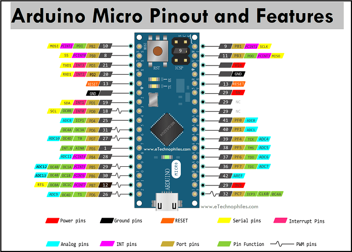
Arduino Micro
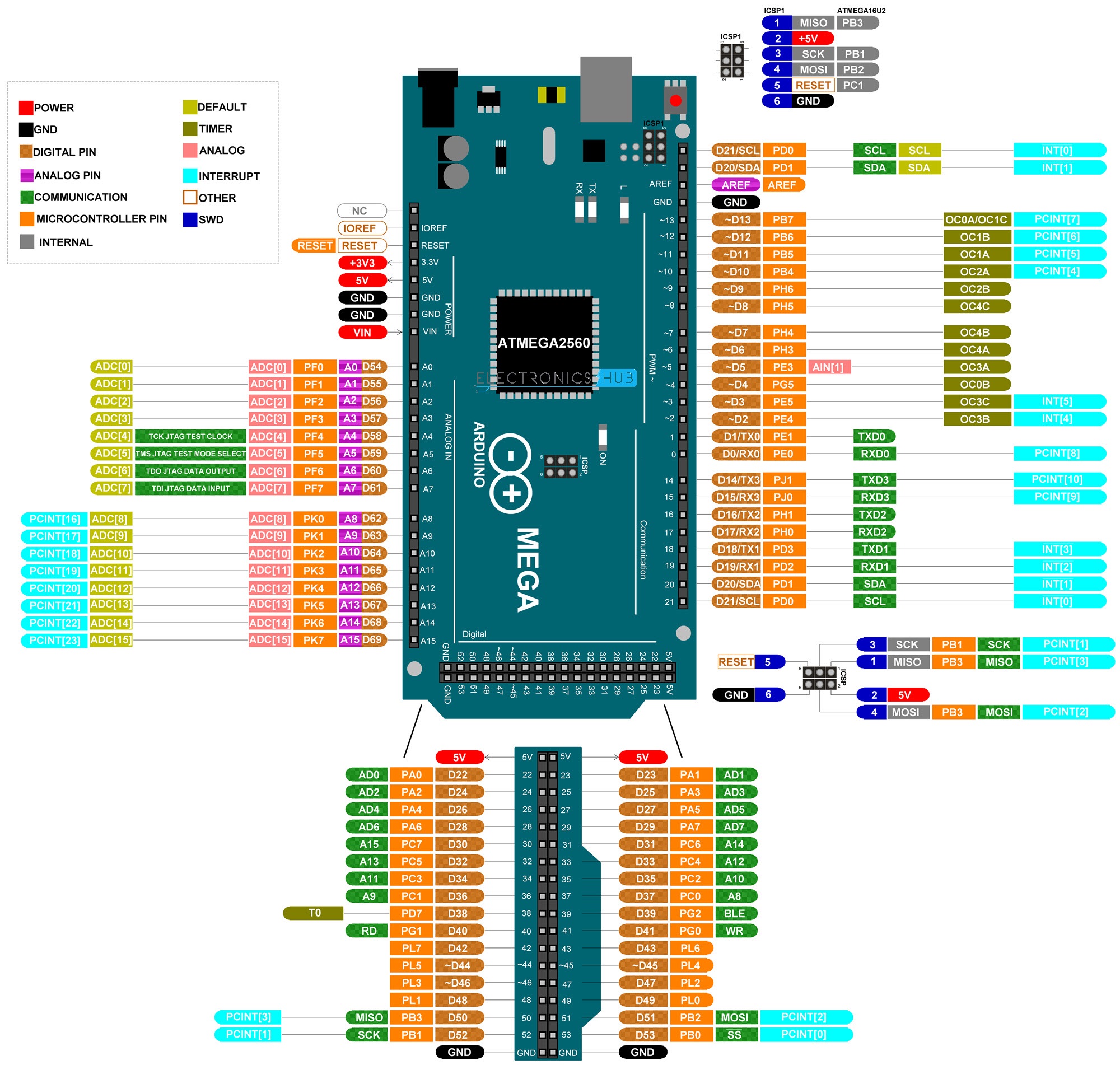
Arduino Mega
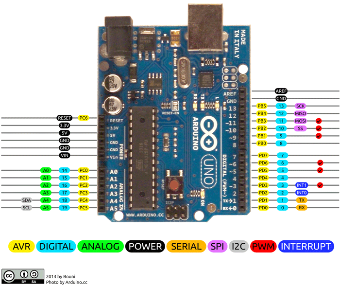
Arduino
Pin 0 and 1 are connected by 10k resistors to the serial hardware so cannot be used, pin13 instead is used for a led.
Links
- [https://rheingoldheavy.com/category/education/fundamentals/arduino-from-scratch-series/
- The Untold History of Arduino
- Play melody