Cookbook
Some recipes of common used circuits.
Add voltage
- Answer to Naively mixing two (or perhaps more) audio signals.
Reverse polarity
Normally you would use a diode to protect your circuit from reverse polarity but has some problems
- voltage drop
- power consumption
A more efficient way is to use P-FETs (source here) but also it has some voltage drop and has a larger footprint.
See also this link from instructables and this video.
Voltage conflict management
Expand using this link about implementation in Arduino.
Inductive spike
A flyback diode can be used to limit damage when an inductive load uses a varying current (source).
PWM to analog
It's possible to use a simple RC filter to transform a digital signal (modulated with pulse modulation) into a analog signal.
This is done taking into account the spectrum of the square wave (with a 1Mhz PWM the harmonics occur at 1MHz, 2MHz, 3MHz and so on).
(source)
http://www.allegromicro.com/en/Design-Center/Technical-Documents/Hall-Effect-Sensor-IC-Publications/Method-for-Converting-a-PWM-Output-to-an-Analog-Output-When-Using-Hall-Effect-Sensor-ICs.aspx
/*
 Generating a tone using DDS
*/

unsigned int Acc;
unsigned int Note = 857; // Middle C

void setup() {
  // Enable 64 MHz PLL and use as source for Timer1
  PLLCSR = 1<<PCKE | 1<<PLLE;

  // Set up Timer/Counter1 for PWM output
  TIMSK = 0;                     // Timer interrupts OFF
  TCCR1 = 1<<CS10;               // 1:1 prescale
  GTCCR = 1<<PWM1B | 2<<COM1B0;  // PWM B, clear on match

  pinMode(4, OUTPUT);            // Enable PWM output pin

  // Set up Timer/Counter0 for 20kHz interrupt to output samples.
  TCCR0A = 3<<WGM00;             // Fast PWM
  TCCR0B = 1<<WGM02 | 2<<CS00;   // 1/8 prescale
  TIMSK = 1<<OCIE0A;             // Enable compare match, disable overflow
  OCR0A = 49;                    // Divide by 400
}

void loop() { }

ISR(TIMER0_COMPA_vect) {
  Acc = Acc + Note;
  OCR1B = (Acc >> 8) & 0x80;
}
Waveform Generation using an ATtiny85
Transistor Schmitt Trigger
The Schmitt Trigger is a logic input type that provides hysteresis or two different threshold voltage levels for rising and falling edge. This is useful because it can avoid the errors when we have noisy input signals from which we want to get square wave signals.
- http://howtomechatronics.com/how-it-works/electrical-engineering/transistor-schmitt-trigger/
Logic level converter
There are parts of your circuit that work at different voltage levels, and connecting them together can cause damaging it; the correct way to handle this situation is to place a level shifter/converter between them.
A simple implementation is using a N-Channel MOSFET in the following configuration
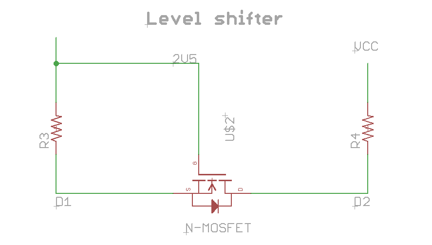
For the resistors in this schematics there isn't a precise value, some use 4.7k but following this page there are several different values that are correct. The original application note 97055 from Philips says
Values of pull-up resistors and series resistors are not given here, they depend on the worst case values of the supply voltages and logic levels, length and load of the bus lines, and the requirements for rise and fall times. These resistors have to be calculated for each bus system separately. A good approach for the calculation is to keep the RC values for the different sections about the same, it gives the best timing tolerances for set-up and hold times.
- Adafruit's product following this design
- Sparkfun's product
- Application note 97055
- Application note 10441
Single supply microphone amplifier
TODO: from page 261 of AoE.
Virtual ground
Octopus tester
This is a circuit to draw with an oscilloscope in X-Y mode the voltage/current graph of
a component.
- Analog Signature Analysis Using a Curve Tracer PDF