BUS PIRATE
It's a multi-purpose tool to interface with a lot of protocols. It's built on top
a PIC24FJ64GA002 microcontroller. It's all open source (github repo)
and the PIC can be programmed following this post.
A note about versioning: exist three different versions:
- the hardware
- the firmware
- the bootloader
In order to use bus pirate you have to connect to it with a serial terminal; I will use the terminal
included with the PySerial (# pip install pyserial)
$ python -m serial.tools.miniterm /dev/ttyUSB0 --baud=115200 --lf
(if you want is possible to use screen: screen /dev/ttyUSB0 115200 8N1).
Follow the cable pinout
In order to connect to the an UART port
$ python -m serial.tools.miniterm /dev/ttyUSB0 --baud=115200 --lf
--- Miniterm on /dev/ttyUSB0: 115200,8,N,1 ---
--- Quit: Ctrl+]  |  Menu: Ctrl+T | Help: Ctrl+T followed by Ctrl+H ---
    Hiz>i
    Bus Pirate v3a
    Firmware v5.10 (r559)  Bootloader v4.4
    DEVID:0x0447 REVID:0x3046 (24FJ64GA002 B8)
    http://dangerousprototypes.com
    CFG1:0xFFDF CFG2:0xFF7F
    *----------*
    Pinstates:
    1.(BR)  2.(RD)  3.(OR)  4.(YW)  5.(GN)  6.(BL)  7.(PU)  8.(GR)  9.(WT)  0.(Blk)
    GND         3.3V    5.0V    ADC VPU AUX -   TxD -   RxD
    P           P   P   I   I   I   I   I   I   I
    GND         0.00V   0.00V   0.00V   0.00V   L   L   H   L   L
    Power supplies OFF, Pull-up resistors OFF, Normal outputs (H=3.3v, L=GND)
    MSB set: MOST sig bit first, Number of bits read/write: 8
    a/A/@ controls AUX pin
    UART (spd brg dbp sb rxp hiz)=( 8 34 0 0 0 0 )
    *----------*
Pinouts
Exist different versions of cable colors, in this text we use the seeedstudio one
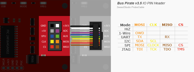
Mode
There is a tricky behaviour with pullup resistor and open collector mode and normal pin mode, read more here.
Bus modes
HiZ
In this mode all the pins are set as high impedence.
1-Wire
Utilities
Power supply
With the w/W it's possible to de/activate the power supply (it's not possible
in HiZ mode).
ADC reading
The ADC pin can read voltage using the d or D command.
1-WIRE>D
VOLTMETER MODE
Any key to exit
VOLTAGE PROBE: 2.10V
Bootloader
The BP has a bootloader, in hardware v3 can be accessed with the pirate-loader console
program that you can found in this repomoved to github.
To activate the bootloader you have to connect the pins PGC PGD like the
image below:
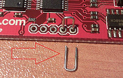
Otherwise is possible to activate it from the console itself
HiZ>$
BOOTLOADER
Remember to turn off your terminal to free the serial port before proceeding. If the process fail for some reason, you can always reactivate it with the jumpers.
$ sudo ./pirate-loader_lnx --dev=/dev/ttyUSB0 --hello
+++++++++++++++++++++++++++++++++++++++++++
  Pirate-Loader for BP with Bootloader v4+
  Loader version: 1.0.2  OS: Linux
+++++++++++++++++++++++++++++++++++++++++++

Opening serial device /dev/ttyUSB0...OK
Configuring serial port settings...OK
Sending Hello to the Bootloader...OK

Device ID: PIC24FJ64GA002 [d4]
Bootloader version: 1,02
UART
It's also possible to set custom baud rates entering the appropriate raw UXBRG register value.
Logic Analyzer
- http://www.hobbytronics.co.uk/bus-pirate-logic-sniffer
- http://codeandlife.com/2012/05/05/logic-analysis-with-bus-pirate/
- https://github.com/syntelos/jlac
- http://www.lxtreme.nl/ols/
| channel | input | color |
|---|---|---|
| 0 | CS | red |
| 1 | MISO | brown |
| 2 | CLK | yellow |
| 3 | MOSI | orange |
| 4 | AUX | green |
| GND | black |
Oscilloscope
- https://github.com/tgvaughan/PirateScope
SPI
Here below a simple script to use the raw SPI mode and read the JEDEC of a flash chip
#!/usr/bin/env python3
# http://dangerousprototypes.com/docs/SPI_(binary)
import sys
from serial import Serial
import time


def wait():
    time.sleep(1)


def bp_reset(ser):
    ser.write(b"\x0f")
    wait()

    print(ser.read(ser.in_waiting))


def bp_enter_bitbang_mode(ser):
    # enter bitbang mode
    [ser.write(b"\x00") for _ in range(20)]
    wait()

    print(ser.read(ser.in_waiting))


def bp_enter_spi_mode(ser):
    ser.write(b"\x01")
    wait()

    print(ser.read(ser.in_waiting))


def bp_exit_spi_mode(ser):
    ser.write(b"\x00")
    wait()

    print(ser.read(ser.in_waiting))


def bp_setup(ser):
    ser.write(bytearray([0b10001000]))
    wait()
    print("setup 3v3: %s" % ser.read(ser.in_waiting))

    # ser.write(bytearray([0b01001000]))
    ser.write(b"\x4b")
    wait()
    print("setup power %s" % ser.read(ser.in_waiting))

    # Set SPI config: output type, idle, clock edge, sample
    ser.write(b"\x88");
    wait()
    print("setup clk %s" % ser.read(ser.in_waiting))


def bp_send_receive(ser, data, output_size):
    packet = b"\x04\x00\x01\x00\x03\x9f"
    ser.write(packet)
    wait()

    print("CHIP ID %s" % ser.read(ser.in_waiting).hex())


if __name__ == '__main__':
    s = Serial(sys.argv[1], int(sys.argv[2]))

    bp_enter_bitbang_mode(s)
    bp_enter_spi_mode(s)
    bp_setup(s)
    bp_send_receive(s, None, 10)
    bp_exit_spi_mode(s)

    bp_reset(s)
I2C
Example with the ADXL345
Following the datasheet, this device has a frequency of 400KHz.
We will try to read the device id that is at address 0x00, should return a value of 0xE5
I2C>W
POWER SUPPLIES ON
I2C>(1)
Searching I2C address space. Found devices at:
0xA6(0x53 W) 0xA7(0x53 R)
I2C>[ 0xA6 0x00 [ 0xa7 r ]
I2C START BIT
WRITE: 0xA6 NACK
WRITE: 0x00 NACK
I2C START BIT
WRITE: 0xA7 ACK
READ: 0xE5
NACK
I2C STOP BIT
Register 0x2D—POWER_CTL (Read/Write) its reset value is 0x00, the
important bit is the measure one that reflects the measurement state of the
sensor. It's the third bit.
I2C>[ 0xa6 0x2d [ 0xa7 r ]
I2C START BIT
WRITE: 0xA6 ACK
WRITE: 0x2D ACK
I2C START BIT
WRITE: 0xA7 ACK
READ: 0x00
NACK
I2C STOP BIT
so, uin order to read something we set to 1 the measure bit
I2C>[ 0xa6 0x2d 0b00001000]
I2C START BIT
WRITE: 0xA6 ACK
WRITE: 0x2D ACK
WRITE: 0x08 ACK
I2C STOP BIT
But the most interesting part is the reading of the actual accelerometer values:
from register 0x32 to 0x37: we put the accelerometer with the z-axes
pointing upward
I2C>[ 0xa6 0x32 [ 0xa7 r:6]
I2C START BIT
WRITE: 0xA6 ACK
WRITE: 0x32 ACK
I2C START BIT
WRITE: 0xA7 ACK
READ: 0x08  ACK 0x00  ACK 0x03  ACK 0x00  ACK 0x00  ACK 0x01
NACK
I2C STOP BIT
- http://www.starlino.com/bus_pirate_i2c_tutorial.html
JTAG
In order to use bus pirate with openocd you need to enable it
git clone git://git.code.sf.net/p/openocd/code
cd code
./bootstrap
./configure --enable-maintainer-mode --disable-werror --enable-buspirate
make
sudo make install
Some informations can be found here.
The cable connection are documented here
| BP | JTAG | color |
|---|---|---|
| VPU | VTRef(3v3) | blue |
| GND | GND | black |
| MOSI | TDI | violet |
| MISO | TDO | grey |
| CLK | TCK | yellow |
| CS | TMS | red |
| N/A | TRST | |
| N/A | RTCK | |
| AUX | SRST | green |
Links
- http://cybermashup.com/2014/05/01/jtag-debugging-made-easy-with-bus-pirate-and-openocd/
- Recovering DGN3500 with the Bus Pirate Post pretty recent
- http://bgamari.github.io/posts/2012-03-28-jtag-over-buspirate.html
AVR Programming
Can be used with avrdude as is with the following command
$ avrdude -c buspirate -p atmega32u4 -P /dev/ttyUSB0 -b 115200
or is possible to use an alternative firmware in order to emulate the STK500
$ avrdude -c stk500v2 -P /dev/ttyUSB0 -b 115200
PIC 24FJ64GA002 development board
Links
- http://dangerousprototypes.com/docs/Practical_guide_to_Bus_Pirate_pull-up_resistors
- http://nada-labs.net/2010/using-the-buspirate-with-a-sd-card/
- Reading from SDHC card using the Bus Pirate post by hackaday
- http://wiki.yobi.be/wiki/Bus_Pirate
- https://code.google.com/p/the-bus-pirate/wiki/BusPirate102
- AVR Bus-Pirate-a-like github